DIY Self Driving - Part 4. Steering
Please Note: Unlike
most of my projects which are fully complete before they are published,
this project is as much a build diary as anything else. Whilst I am
attempting to clearly document the processes, this is not a step-by-step
guide, and later articles may well contradict earlier instructions.
If you decide you want to duplicate my build, please read through all the relevant articles before you start.
Here is where we get into the mechanical complexities of our project. If you don't understand how motor car steering works, I would suggest Allan Staniforth's "Competition Car Suspension" and Tony Pashley's "How to build Motorcycle-Engined Racing Cars" but suffice to say my car has a very simplified design which approximates a steering rack in that it translates the rotary movement of the steering column into a linear movement which pushes/pulls the steered wheels about their pivot points.
Instead of a pinion gear driving the rack movement, this car uses a lever arrangement which I have called a "J-Bar" because it's shaped like the letter "J":

 While this might look crude it is close to ideal for our purposes. I am planning on using a very heavy duty servo motor to replicate the function. I am confident that if I can mount the servo in plane with the rack then I can link it using a custom horn (those little bits which attach to the top of the servo) directly to the rack.
The "hobby" or "micro" servos typically have a torque value of 9g/cm. In other words, at the end of a 1cm long arm (measured from the centre of the motor shaft) it could lift a 9 gram mass.
As a simple demonstration, hook one up to an Arduino and run the servo sweep example. You can stop it in your fingers. Or if you modify the program to set the position to 90 degrees, it is not difficult to move the horn. The servo will correct this, but you can gauge the strength.
My car weighs about 8Kg all up. If it were perfectly balanced this would mean 2Kg sits on each wheel. As it turns out the weight is biased about 60% to the rear. This means there is about 1.6Kg on each front wheel. If my maths is even close to right I think that the 9g servo motor is going to have problems with the 3.2Kg of mass it has to move. I expect the nylon gears would strip very soon.
Don't despair, there is a solution. Wading through online catalogues showed there was a range of larger servos available. I decided to go all-in and get a 20Kg/cm model. Curiously its cost as about $45, so 4.5 times the price gets me 2000 times the torque. It also has metal gears which should make it much more durable.
I ran some early tests and discovered two things:
With the wheel out, there was a bent pin on the other end of the J-bar which needed to be removed and then the whole thing slid out.


It really helps to have string which is a strong colour contrast when you're doing this. Firstly mark your centre line and run a length of string down it. Centre the steering and check that the hole in the bar lines up on this line.
Now set the steering to full lock on one side and bring a string line from the position back to your estimated servo location. Repeat for the other side as well.
In reality, what we have laboured to prove over the last 15 or so minutes is that the designer got it right in the first place! However, it's not wasted because when we mount our servo the hole is not visible.
You might also notice I had to relocate the wiring coming out of the pedal compartment to clear my mounting block. This meant cutting down the old tie point and sanding it level with the rest of the body.
I fitted a second timber to each side of the servo motor to enclose it and prevent it from twisting under load when the car is on its wheels.
With that part done, I attached a piece of aluminium angle to the long sides of the block and screwed the servo to that using M3 screws and nuts. Since it's going to be really hard to get to later, I added some "locktite" thread adhesive for peace of mind.
The completed assembly could be painted to make it look nicer, but I didn't bother since I don't expect this car to roll over all that often. When you're happy with everything it can be fixed into place with a series of screws through the body of the car.
Some might scoff at using wood for this project, but remember Morgan were still building entire chassis from wood well into the 1990's and people consider them to be highly desirable...
Once you have determined the sizes for everything, drill out two of the holes in the servo horn to take M3 screws. You will probably also need to drill the arm to suit. The cable(zip) ties in the photo were simply to hold things in place while I shaped everything. They will definitely not hold it securely enough to function. (I tried).
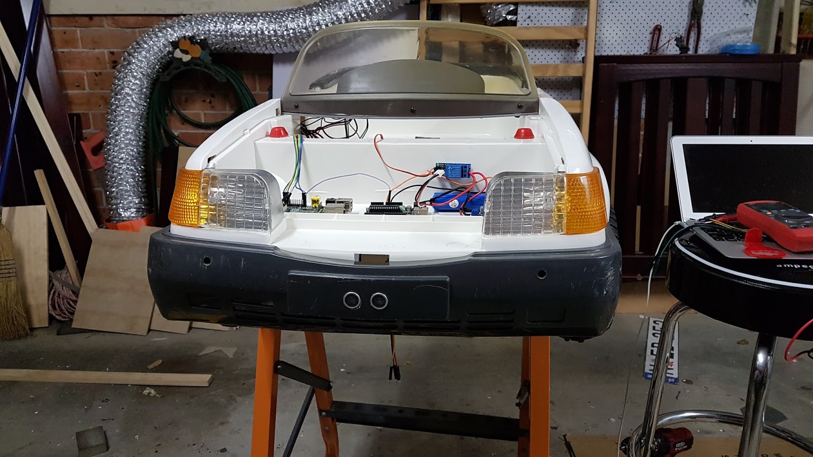
I have decided to offload steering control from the Raspberry Pi onto an Arduino Uno board, partly because coding servo functions is something I have done before on that platform and because the Pi is busy enough with image processing.
To test everything, I wrote two small sketches: "servo_test" cycles the steering from side to side, and is very useful for impressing sceptics. "servo_calibrate" allows you to step the steering from side to side and find the limit positions. It will then save these values to the on-board EEPROM for the main steering controls to use.
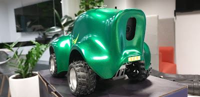
With all this done, you now really have something to show for your efforts. You can see mine in the video here:
Finally, put it back over onto it's wheels and take more photos of your hard work!

Further Reading
Part 1 - Introduction
Part 2 - Preparing the car
Part 3 - Wiring Harnesses
Part 5 - Sensors
Part 6 - Software
Part 7 - Final assembly and testing
If you decide you want to duplicate my build, please read through all the relevant articles before you start.
Here is where we get into the mechanical complexities of our project. If you don't understand how motor car steering works, I would suggest Allan Staniforth's "Competition Car Suspension" and Tony Pashley's "How to build Motorcycle-Engined Racing Cars" but suffice to say my car has a very simplified design which approximates a steering rack in that it translates the rotary movement of the steering column into a linear movement which pushes/pulls the steered wheels about their pivot points.
Instead of a pinion gear driving the rack movement, this car uses a lever arrangement which I have called a "J-Bar" because it's shaped like the letter "J":


On the subject of servos...
My application is not that uncommon when you look at R/C cars. However this is rather on the large size, so those little tiny units you can buy for less than $10 and hang off your Arduino are not going to be up to the task.The "hobby" or "micro" servos typically have a torque value of 9g/cm. In other words, at the end of a 1cm long arm (measured from the centre of the motor shaft) it could lift a 9 gram mass.
As a simple demonstration, hook one up to an Arduino and run the servo sweep example. You can stop it in your fingers. Or if you modify the program to set the position to 90 degrees, it is not difficult to move the horn. The servo will correct this, but you can gauge the strength.
My car weighs about 8Kg all up. If it were perfectly balanced this would mean 2Kg sits on each wheel. As it turns out the weight is biased about 60% to the rear. This means there is about 1.6Kg on each front wheel. If my maths is even close to right I think that the 9g servo motor is going to have problems with the 3.2Kg of mass it has to move. I expect the nylon gears would strip very soon.
Don't despair, there is a solution. Wading through online catalogues showed there was a range of larger servos available. I decided to go all-in and get a 20Kg/cm model. Curiously its cost as about $45, so 4.5 times the price gets me 2000 times the torque. It also has metal gears which should make it much more durable.
 |
| The Apple logo of my MacBook Pro gives you and idea of the size... |
- I can't move it with my fingers as I could with the 9g model
- It needs more current than the regulator on an Arduino can provide, so it will need to come off the main battery.
Installation
Before we can install, there is more disassembly. Fortunately in my car this wasn't too hard. The steering wheel is attached to the J-bar by a screw and nut behind the steering wheel itself, not in the wheel as you would find in a car.With the wheel out, there was a bent pin on the other end of the J-bar which needed to be removed and then the whole thing slid out.


Connecting to the steering
Whatever your source of inspiration and self-confidence may be, now is a really good time to call on it, because unless you're using the same car and servo as me, you are pretty much on your own. I am going to take you through my process as a guide to building your steering.Position your servo
We need to fix the servo at a centre point in the car which gives full steering movement in either direction for the same servo position either side of centre. It also needs to be far enough back from the rack part so that small changes in servo position result in small changes in steering angle. To do this, I borrowed a very sophisticated set of tools. A roll of string, tape, rule and pencil. |
| Essential for building a car: String and 3 kinds of sticky tape |
 |
| Marking the centre |
 |
| Your servo goes here! |
Making a servo mount
One thing has been missing from the project so far, and that's power tools. Now we will fix that. My servo motor has a typical short output shaft so I need to mount it well proud of the body of the car. Experimentally, I found that a block of D.A.R. pine I had in the garage moved it far enough forward, so I dummied up the mounting using tape to hold things together. |
| Trial mounting |
I fitted a second timber to each side of the servo motor to enclose it and prevent it from twisting under load when the car is on its wheels.
With that part done, I attached a piece of aluminium angle to the long sides of the block and screwed the servo to that using M3 screws and nuts. Since it's going to be really hard to get to later, I added some "locktite" thread adhesive for peace of mind.
 |
| The finished mounting |
 |
| Mounted hard to the body |
Some might scoff at using wood for this project, but remember Morgan were still building entire chassis from wood well into the 1990's and people consider them to be highly desirable...
Link Arm
Now we need to connect the servo to the steering mechanism, and again some imagination will be required. I deliberately servo below the steering (the J-Bar was above it) because I did not want the lowest point on my car to be a rather expensive motor. To link the two I folded a "Z" shaped arm using a piece of "Make-A-Bracket" steel from Bunnings. The purpose of the Z is threefold:- It makes up for the height mismatch between servo and steering
- Compensates for any misalignment.
- It absorbs shocks transferred back from the wheels which might damage the servo.
 |
| Trial-fitting the steering link |
 |
| The finished product |
To test everything, I wrote two small sketches: "servo_test" cycles the steering from side to side, and is very useful for impressing sceptics. "servo_calibrate" allows you to step the steering from side to side and find the limit positions. It will then save these values to the on-board EEPROM for the main steering controls to use.
With all this done, you now really have something to show for your efforts. You can see mine in the video here:
Finally, put it back over onto it's wheels and take more photos of your hard work!
Further Reading
Part 1 - Introduction
Part 2 - Preparing the car
Part 3 - Wiring Harnesses
Part 5 - Sensors
Part 6 - Software
Part 7 - Final assembly and testing


Comments
Post a Comment